Note: In this tutorial the term "CA glue" (cyanoacrylate) refers to super glue or the equivalent, and the term "roots" refers to the wing fillets on this model. We want to thank Pericles for providing this tutorial for us, and Aaron for producing this great paper model. It's a little bit higher on the difficulty scale than many of our other paper models, but keep in mind that Pericles built this at a much smaller scale by reducing the size on his printer settings. Your model will most likely be printed on 8 pages plus instructions, so it will come out to a scale of 1:32 which is much larger than this example. - Scott Fyn
Assembly Instructions
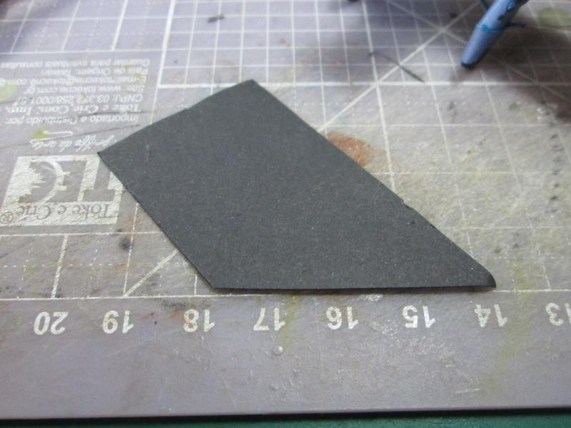
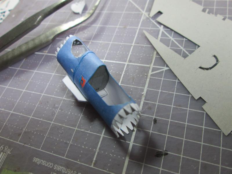
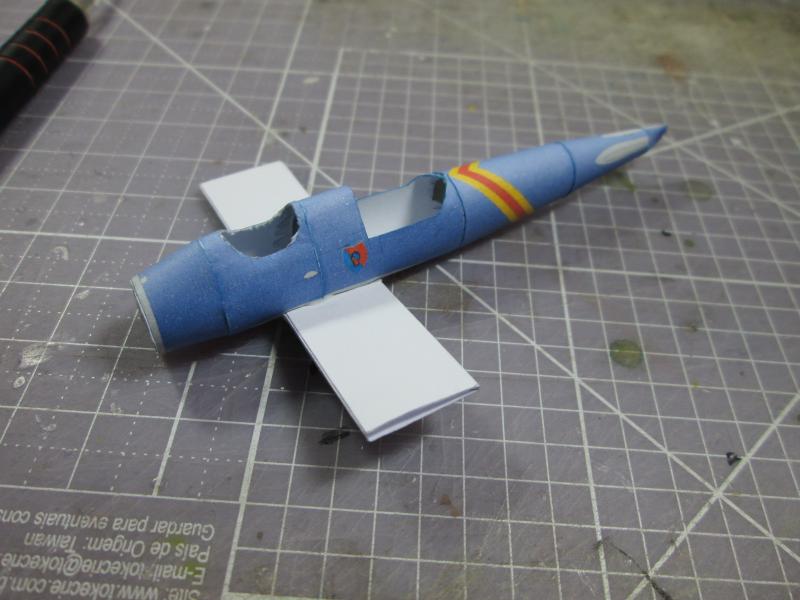
For the assembly, I started by
cutting the fuselage and cockpit formers.
Despite
the fact that the designer does not like these formers, they help simulate the rear walls
of the cockpit and are very useful as they help to provide the proper shape to the
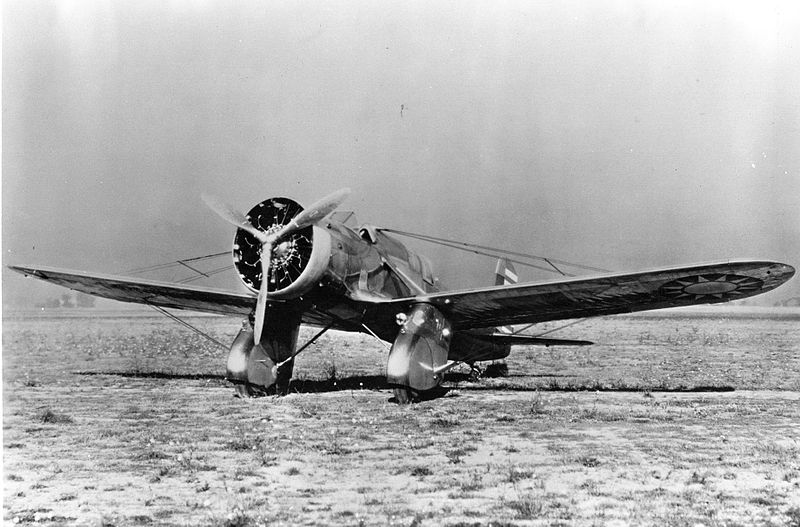
A-12 fuselage. |
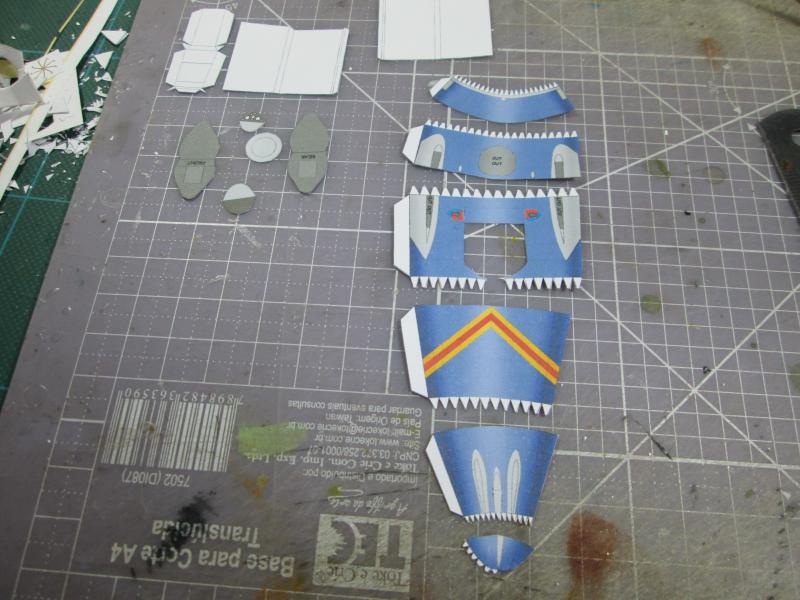 |
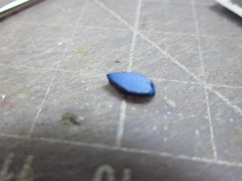
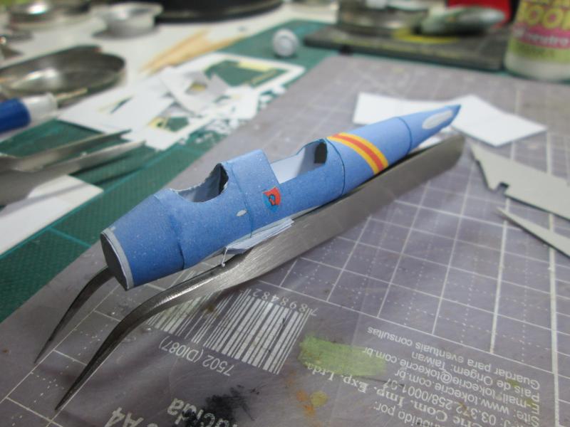
| I painted all the white
edges with blue watercolor... |
 |
| I glued all fuse
segments... |
 |
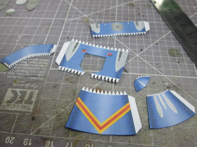
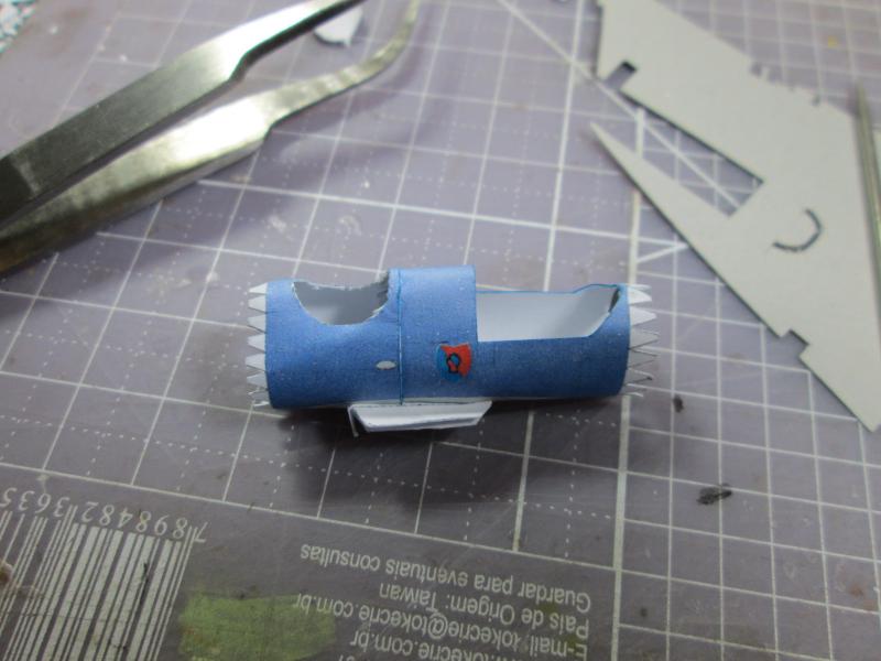
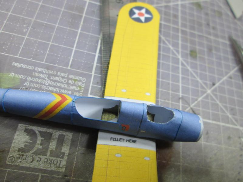
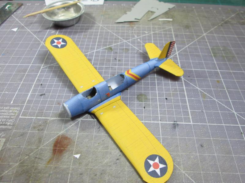
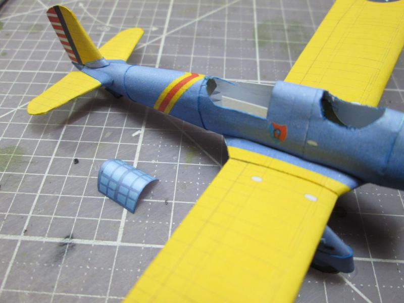
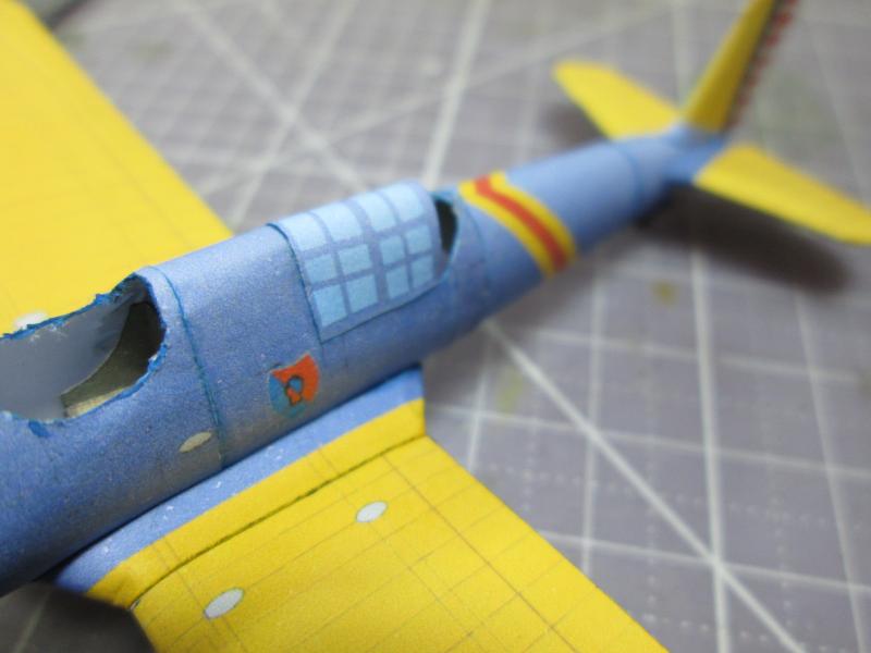
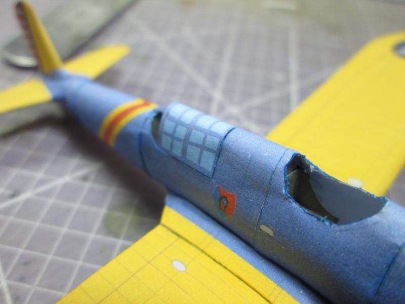
I started by assembling the fuselage center section because of the formers.
These were not laminated. I used the double feature of the part
itself. Two building approaches can be used here: The first is more complicated.
You can cement the formers in the wing root, in positions
that are already marked, and then glue the central segments
of the fuselage. Or you can glue the fuselage in the two central segments,
open holes, insert the wing root and then enter the formers. I opted
for the second possibility. It seemed easier and worked for me.
|
 |
 |
 |
 |
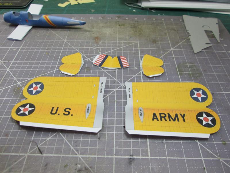
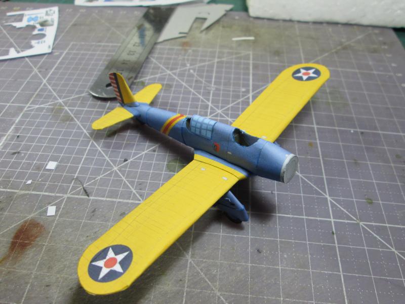
| I prepared the wing surfaces
and built the supports of wings. This provided the correct dihedral. |
 |
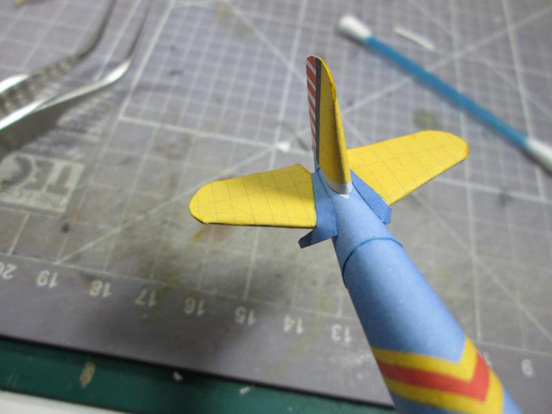
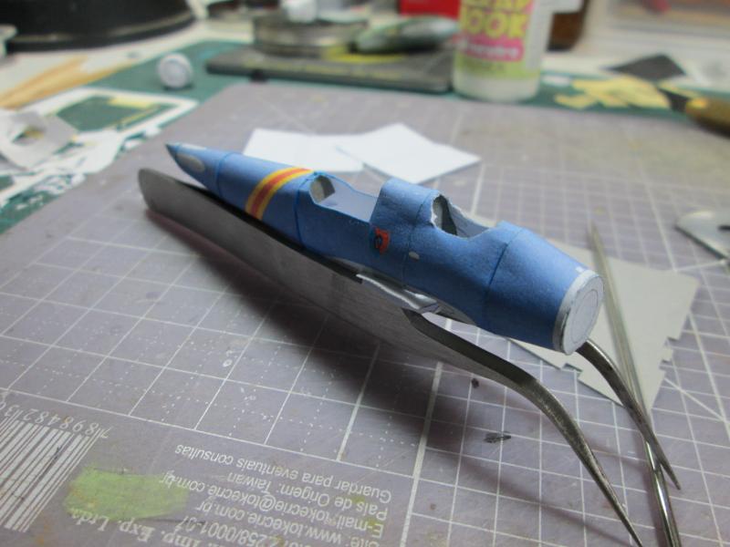
Later,
I cut and prepared the wings, rudders and stabilizers, creasing glue tabs
and painting the white edges with yellow. |
 |
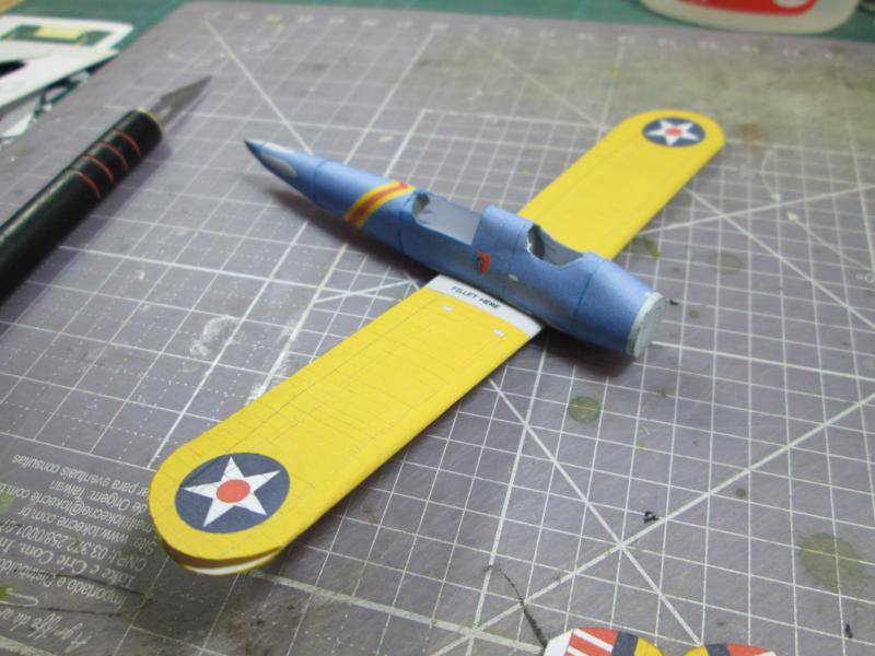
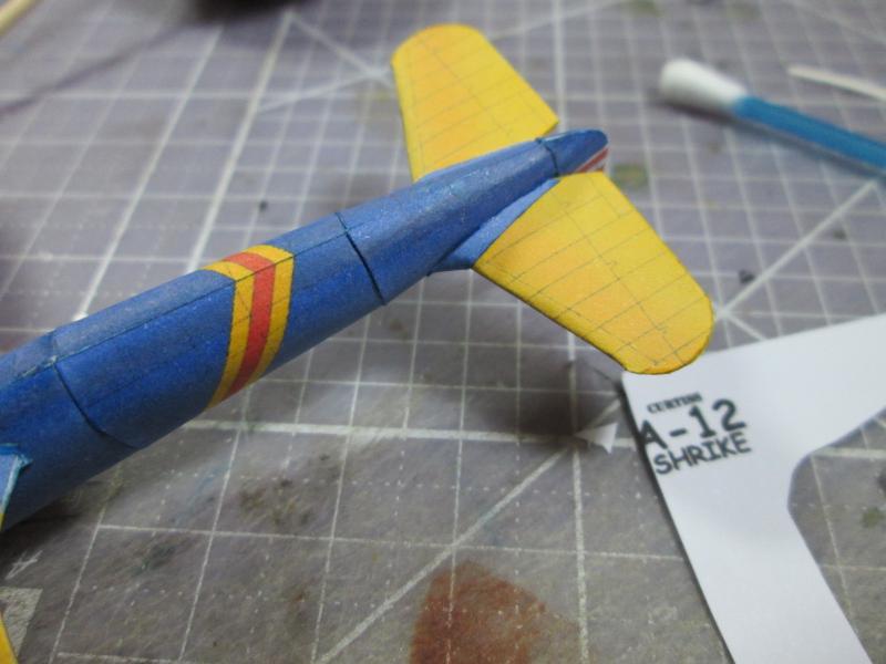
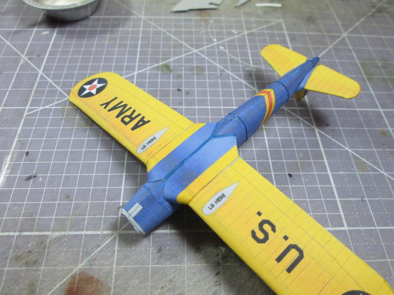
I
started by gluing the wings. They were attached with Styrofoam glue because
it does not cause deformation of the paper when used on large areas.
|
 |
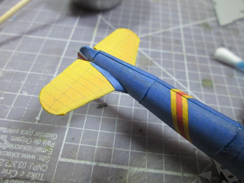
I
mounted the tail smoothly. Note that the edges of both wings of the
tail are not glued yet. This serves to allow for adjustment if necessary. After all was set, I glued the ends. |
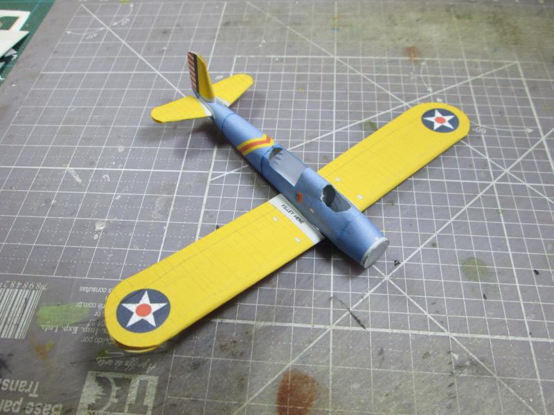 |
Here I made sure the alignment was correct and sealed the wing tips and tail.. |
 |
 |
 |
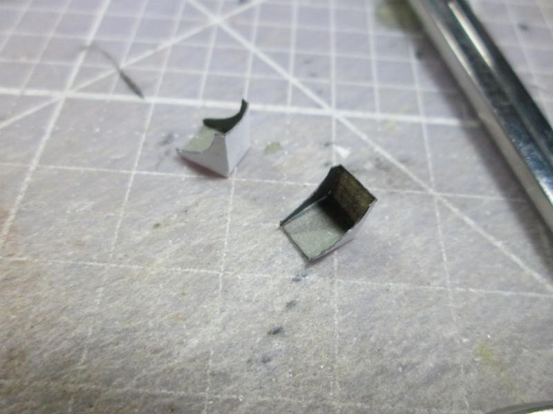
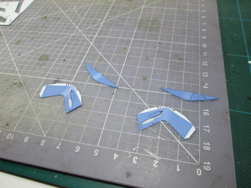
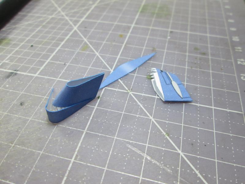
I
made the seats for the pilot and gunner. They are simple pieces that help shape up
the interior. It's always fun to add nice little extras according to the preference of the modeler. |
 |
 |
| Gluing in place |
 |
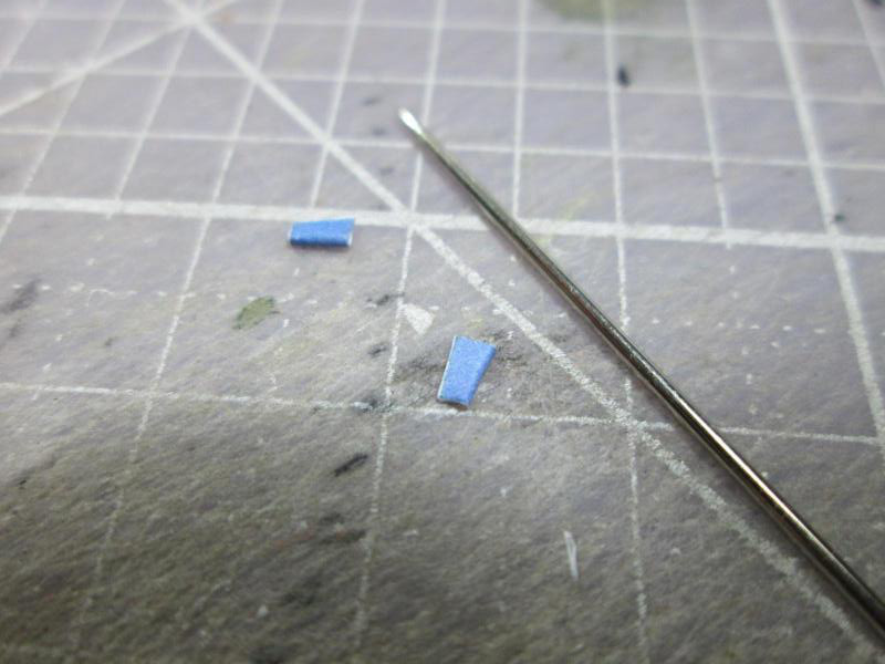
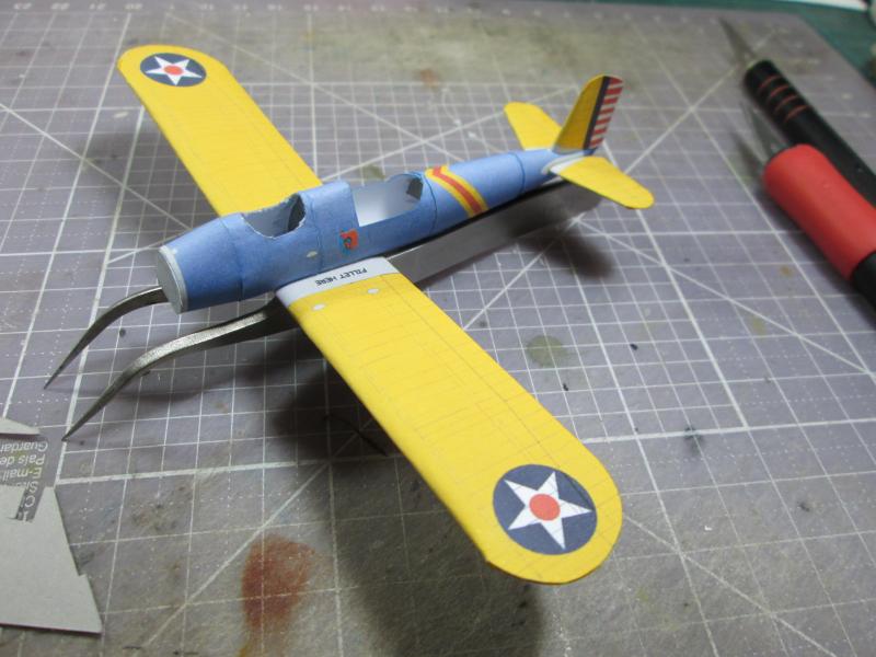
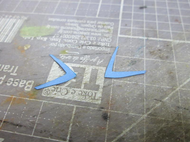
| This section deals with a delicate topic: the roots (called fillets) of all wing surfaces.
Although they are simple pieces they demand a lot of care when you paste them on.
It needs to be just right and shaped perfectly, or else there will be large cracks on
misaligned surfaces. |
 |
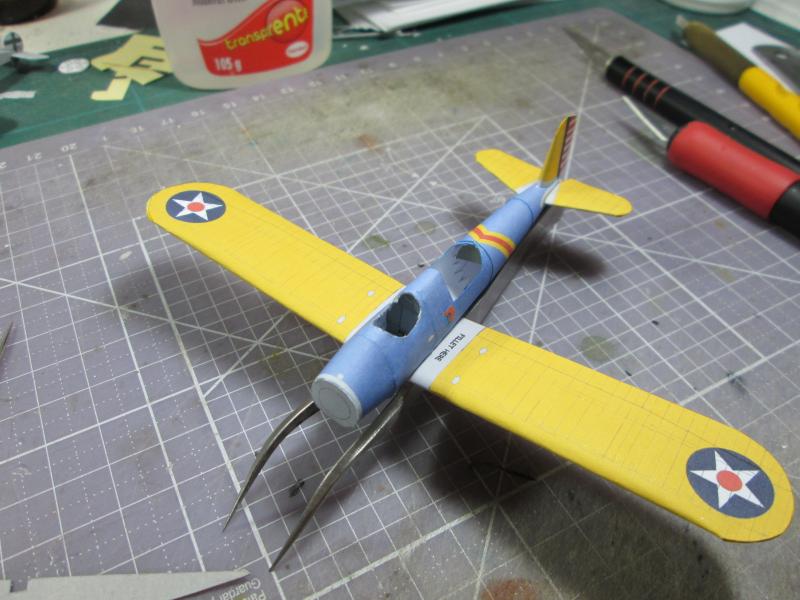
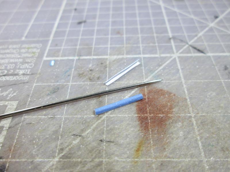
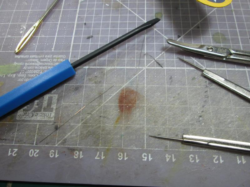
I start
with the base of the wings, usually lapping gradually, starting from the
bottom. It is a delicate task requiring patience. In some cases you will find other
objects to be useful, such as needles, pins or toothpicks to maintain the height of the lines at the time
of bonding, as is the case in this photograph below ... |
 |
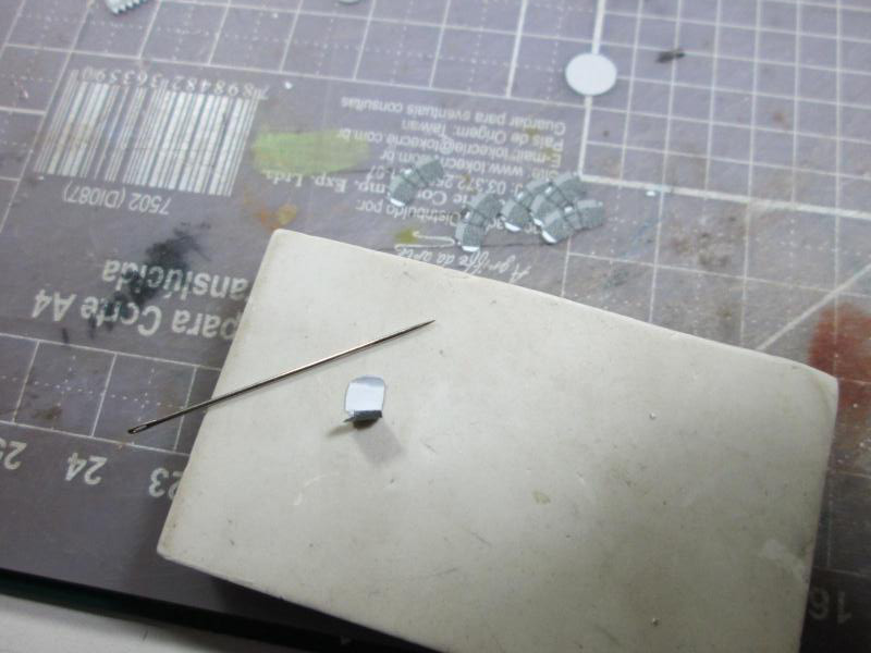
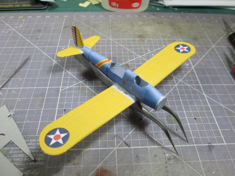
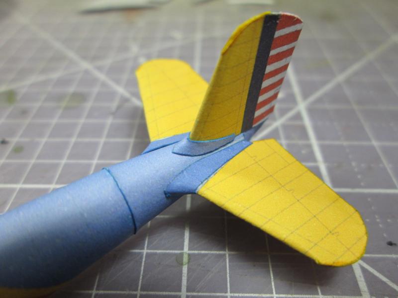
After
a few hours of drying, we did the same procedure with the roots of the stabilizers... |
 |
|
It
is extremely important to use a small portion of glue in this type of
assembly. |
 |
 |
Then
build the root rudder... |
 |
The
results at this time... |
 |
 |
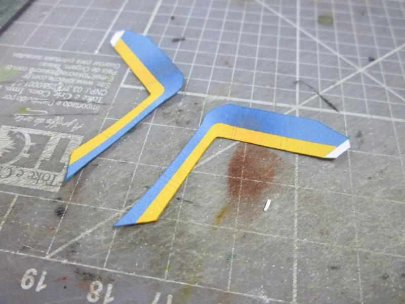
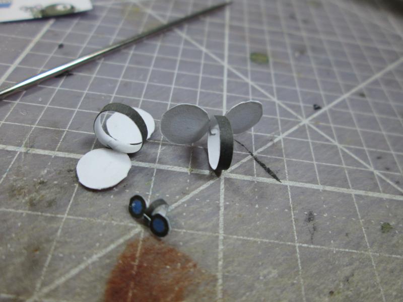
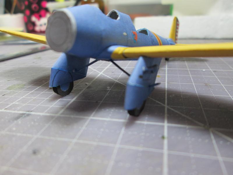
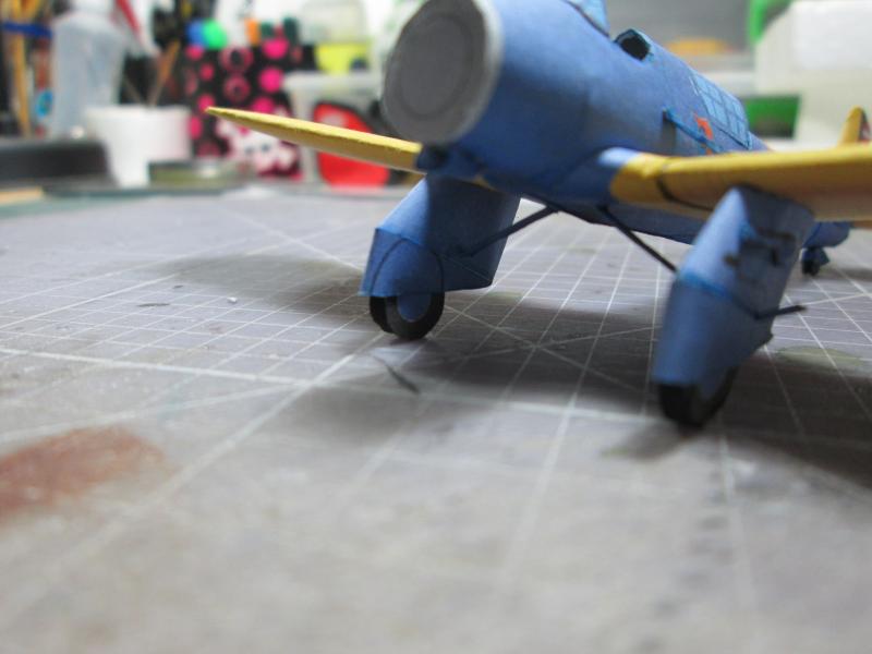
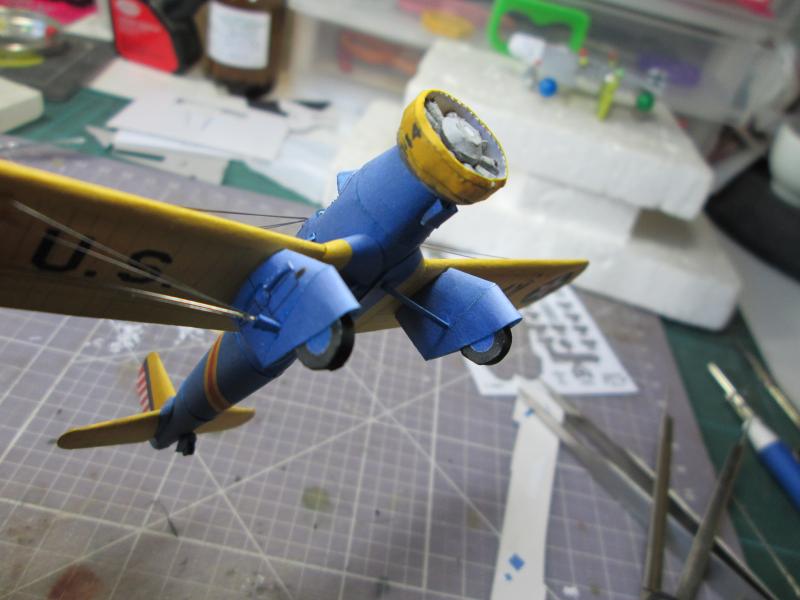
Well
friends, we resumed the assembly with the construction of the pants. They are simple parts that need to be bent and
glued to give a special charm to the whole model. |
 |
Note
that in parts like this bonding should always start with one end ... |
 |
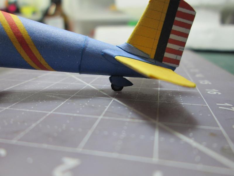
| Tail wheel carriage... |
|
Wheels... |
 |
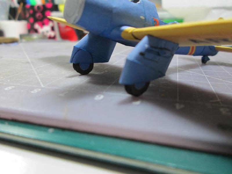
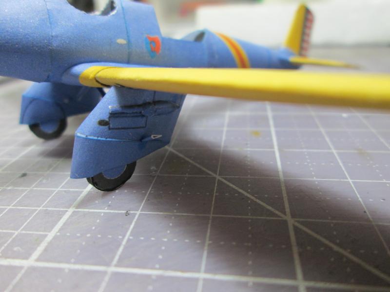
Here
the set of fairings are mounted. I ended up forgetting
to photograph this step, but it is simple as you can see in the photos.
... |
 |
 |
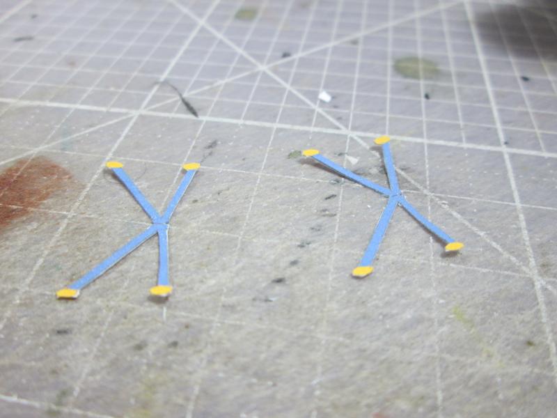
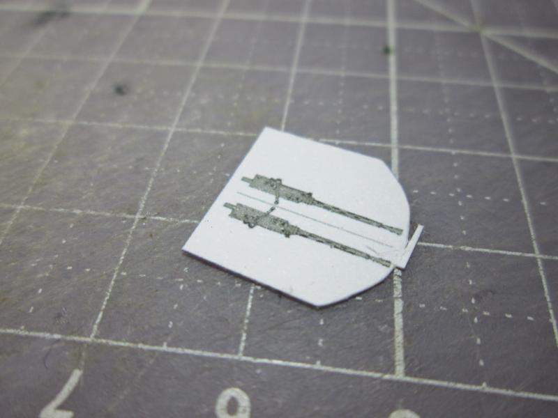
Finalizing
this assembly step, we set off for the details in pants, which consist
of supporting arms and points of fly cables. |
 |
 |
|
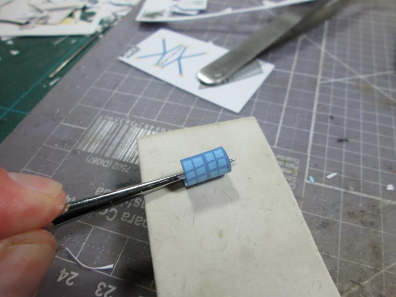
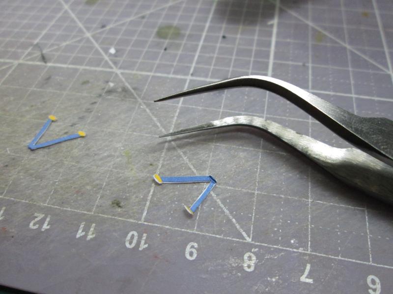
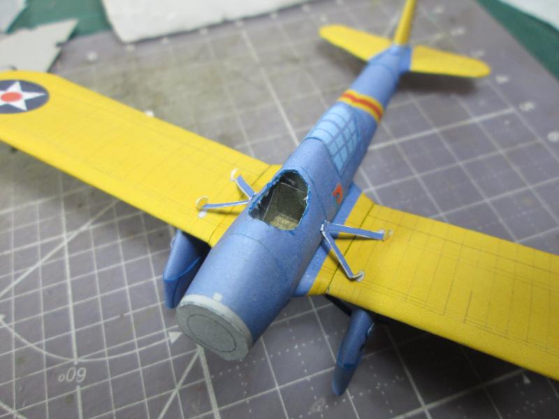
I
use a needle to give a curved shape to this type of piece. |
 |
 |
Here
we see it installed. It's good to check the documentation to
make sure they are exactly in the right place. |
I
left out a small step which is to put a lot of detail on the fuselage,
and the rear canopy. |
 |
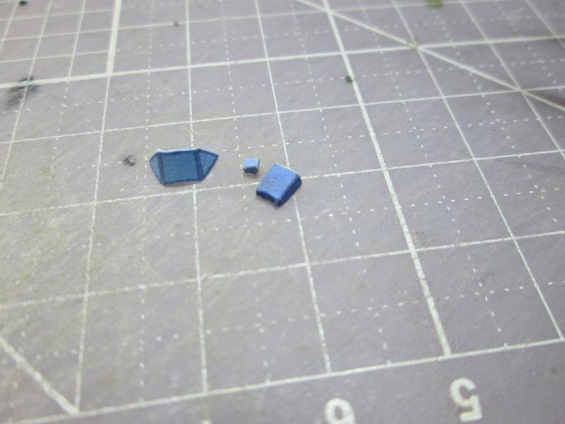
We
started preparing the rear part of the canopy by bending it on a sheet of rubber. |
 |
Note
that the glue area is small. I prepared the tabs, then
fitted and glued the fuselage. |
 |
 |
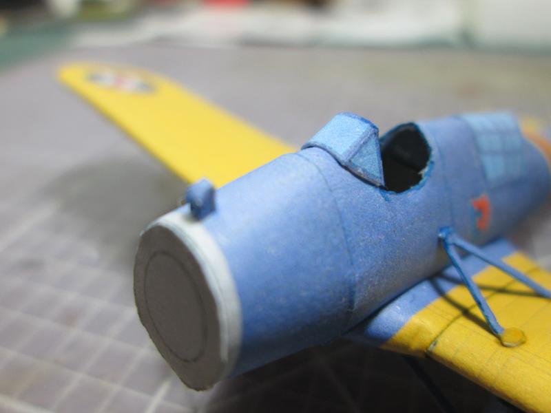
Notice
how this simple measure improves construction. |
 |
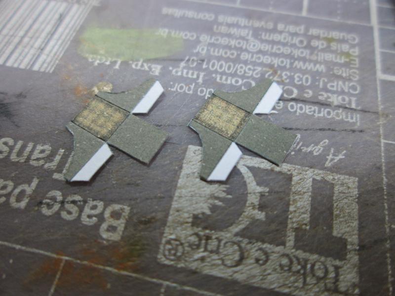
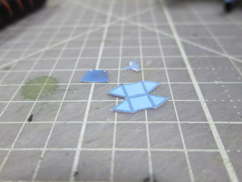
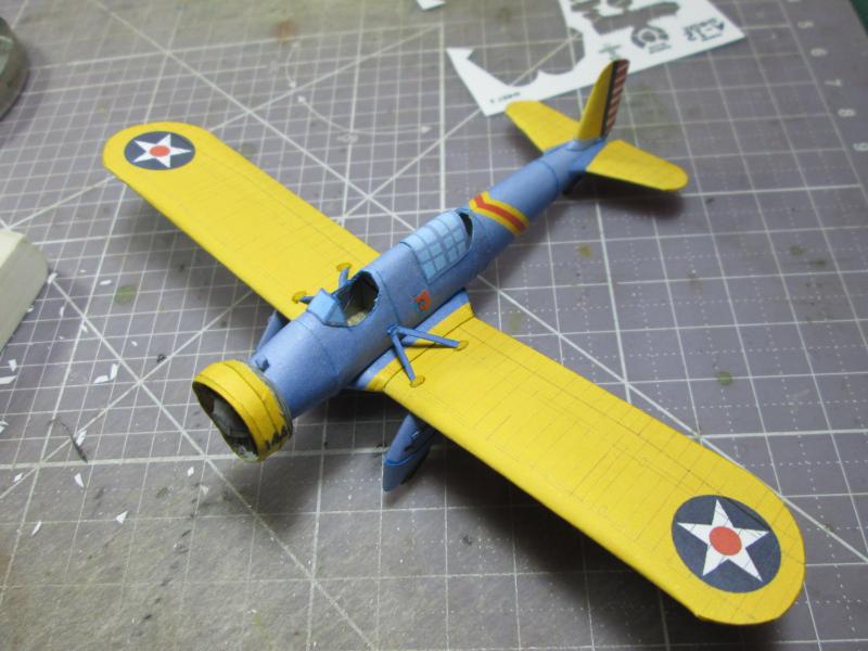
| An
overview of the model so far.
Prepare the wings mounts. They are small parts. Notice that the edges
were folded with tweezers ... |
 |
 |
I
cut the windshield and small engine cowlings ... |
 |
| After the wing mounts dry, glue in the areas indicated by the starting point of the
fuselage, leaving it to dry, and then glue the wings. |
 |
| While it was drying, I mounted the fairing and windshield. |
 |
I
glued the windshield starting at the center of the piece and then the
sides and then the parts of the air intake / engine oil. |
 |
 |
| Aaron
provides a machine gun for the tail gunner, but unlike the A-8, to keep
the clean lines of this Shrike, I opted not to use it. |
 |
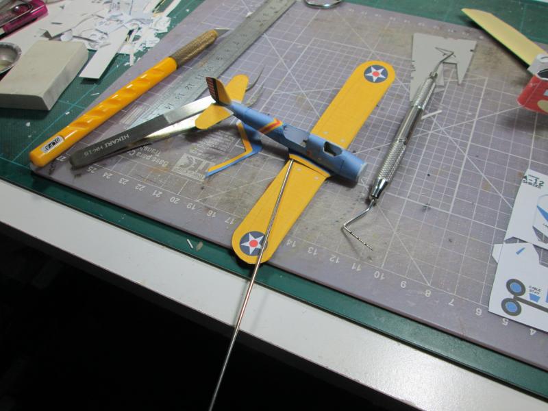
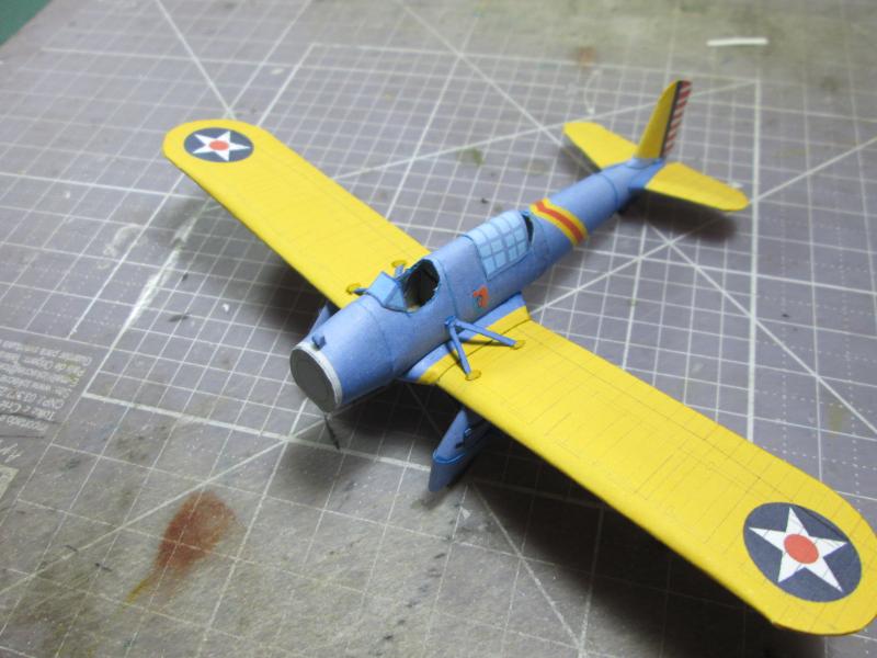
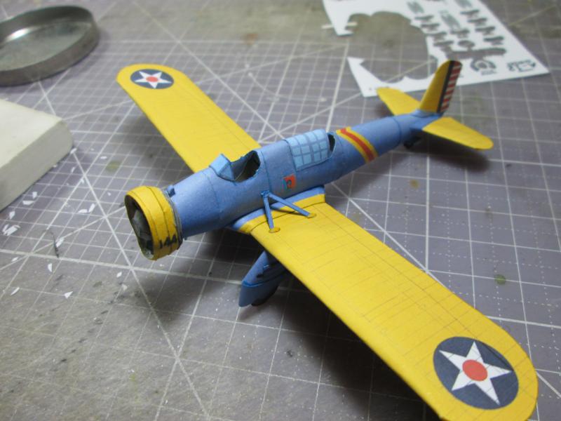
General
aspects. The model is 75% ready ... |
 |
 |
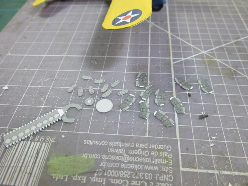
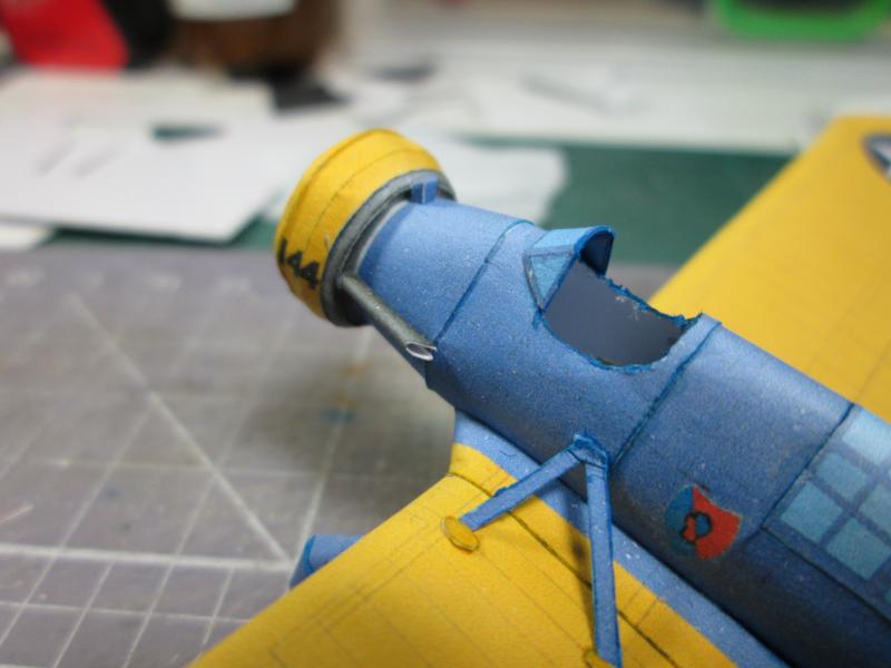
Going
to the final assembly, we begin a very sensitive part, the cyclone engine.
In this model it is very well represented. Start cutting all these
pieces, including the cylinders with their covers,
the gearbox and the block . |
 |
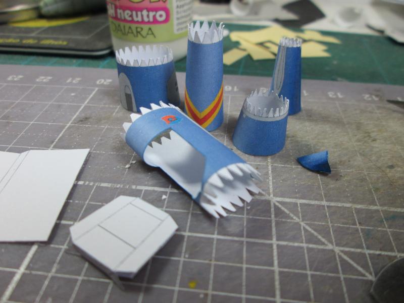
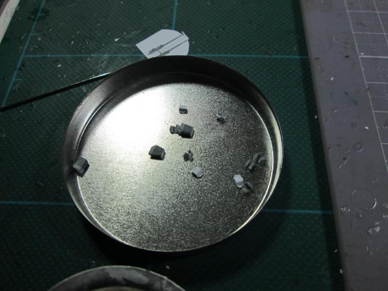
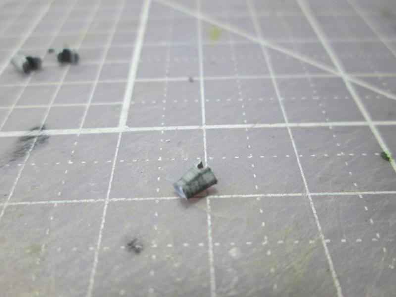
We
started with the assembly of cylinders.
It's repetitive work and you might even say it's tedious, but it's worth it. |
|
 |
 |
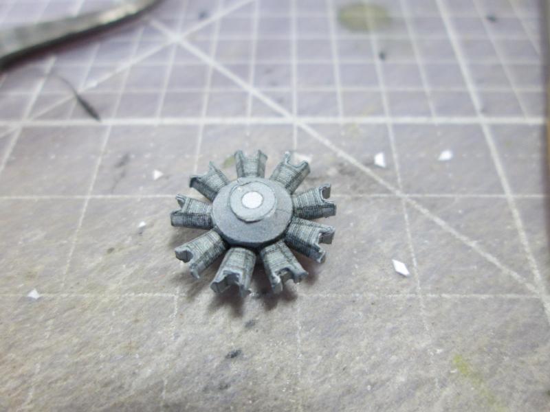
| The finished engine... |
 |
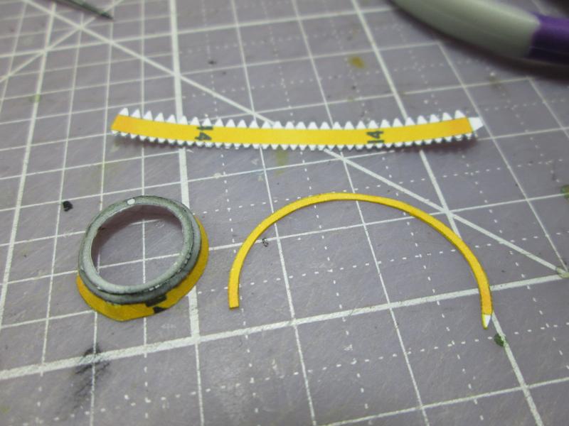
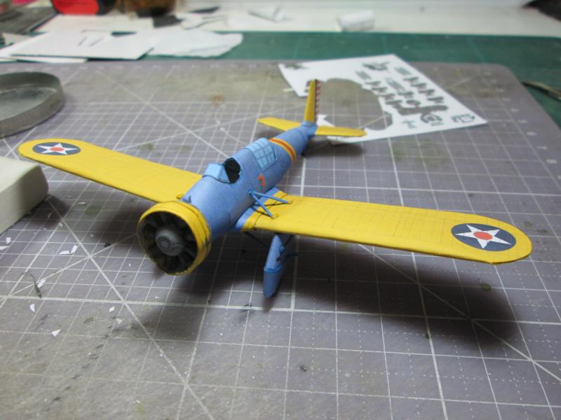
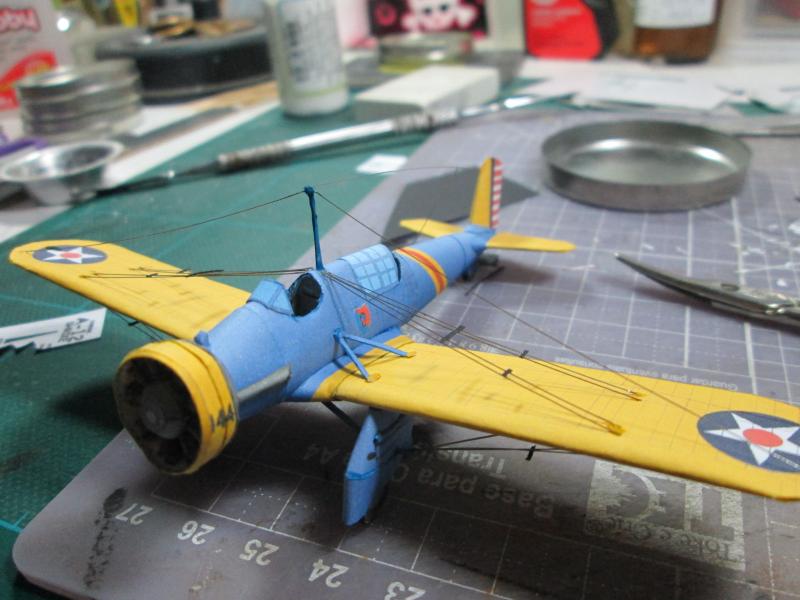
We
then began the cowling, a sensitive part which consists of several
cones and truncated semicones. I started from the back and worked my way to the larger ring in the center. Be very careful while aligning the numerals
on the side. |
 |
 |
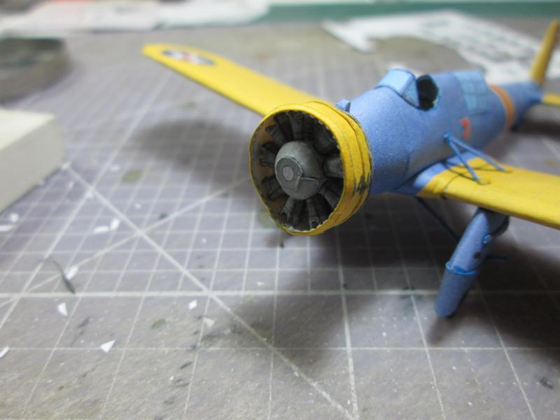
Here I attach, install and glue the last cowling ring of the engine. |
 |
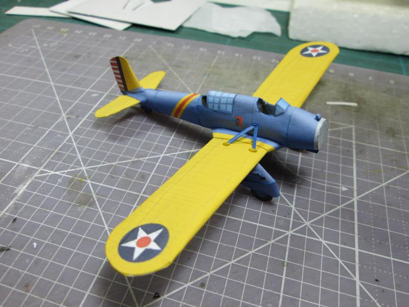
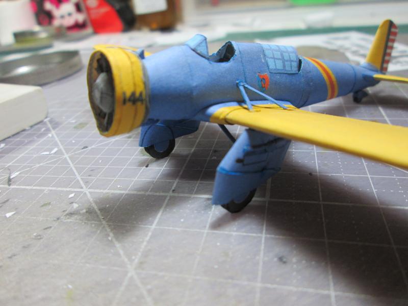
| The model almost
finished ... |
 |
 |
 |
 |
The
exhaust assembly...(I'm not sure if this goes on the right side or the left side) |
 |
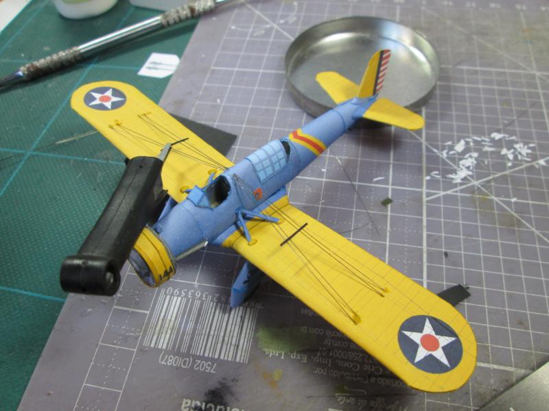
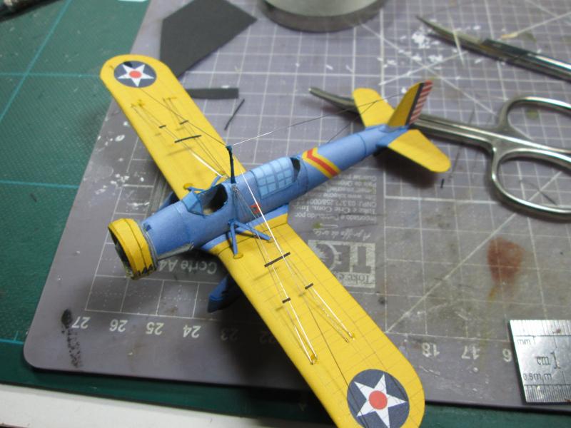
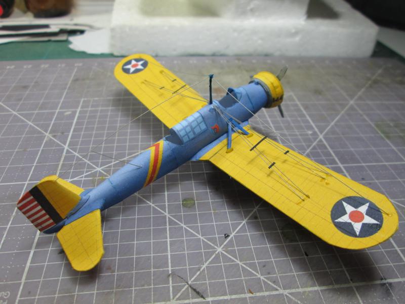
Now
preparing the final details of our model, focusing initially on the
rigging which is quite simple and focuses primarily on the wings. For
those not familiar with my builds, the material I use to simulate the cables is surgical
ligature wire, which is a fairly thin steel. To install it,
cut the thread to the correct length obtained with a compass transfer.
The segment is marked with an electronic tool (used to remove components)
and then cut with nail scissors. |
 |
Observing
the documentation available, I started installing the cables, being
stuck with a small drop of CA glue gel. |
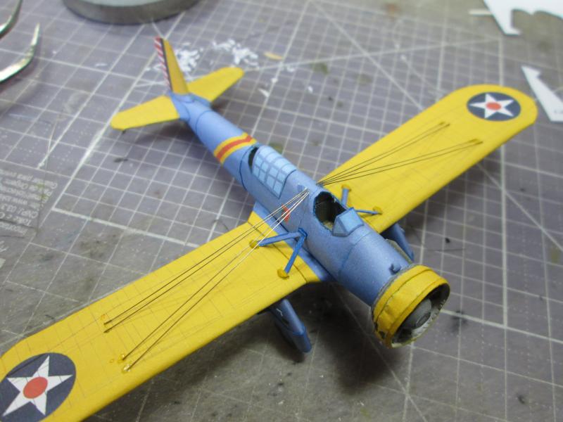 |
Top.. |
 |
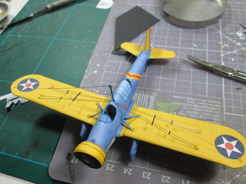
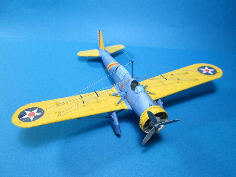
Bottom...
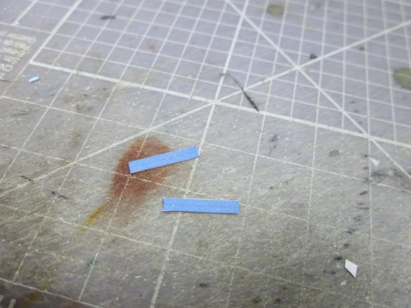
With
a small piece of Vivaldi paper , (pulp colored in black color) I fabricated
cable separators. This is a custom detail, but it gives life
to the model. |
|
With
the help of a small clamp, I installed the separators with CA glue. Again
referring to my documentation, the secret is to build the strips in a
larger size and then cut with scissors to the correct length. |
 |
 |
Finally
I build the antenna mast and installed radio cables. |
 |
 |
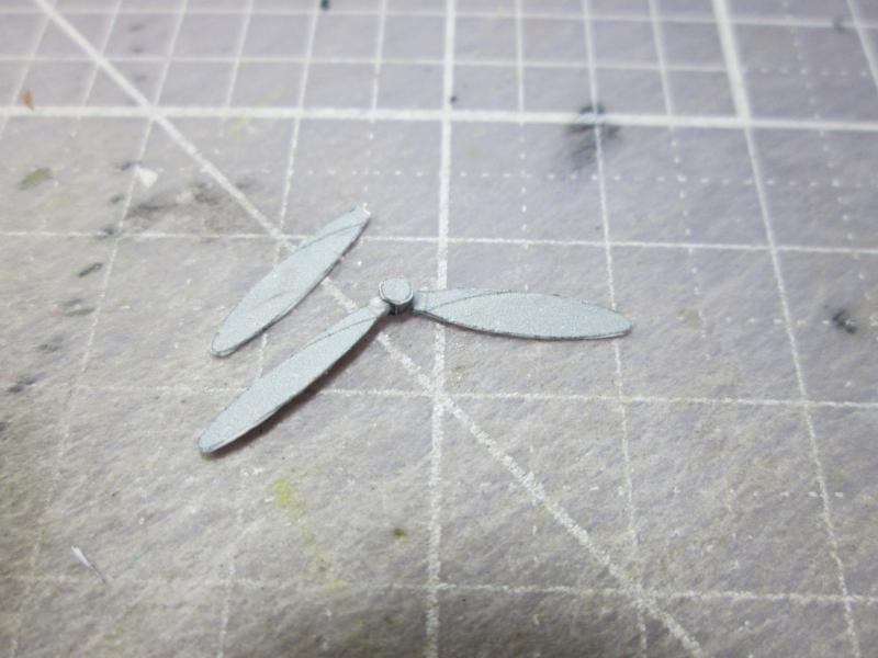
| Last
parts: those that make up the propeller. They are easy to assemble without the
aid of templates because there is the hub, with marks where you glue them in
position. |
 |
Add a
good layer of UV varnish, and it's done! |
 |
 |