Building Fiddler’s Green Models with aluminum cans
Frequently Asked questions and tutorial
What’s the best way to get started working with cans?
In my opinion, paper modeling is the closest medium to what I do with cans. Many, many years ago, I started with the simple patterns here at Fiddler’s Green and quickly adapted them to cans by simply scaling them up about 20% using a pdf editor like Foxit Pdf. Once the size was right, I found that you could simply cut out all of the parts in card stock and use them as templates for tracing onto your cans. To start out, I would recommend downloading a simple jet like the MiG 15, F-117 or the F-86 Sabre from the website and build it out of cardstock first before tackling it in cans. Once you have a good idea how the model goes together in card stock, you should be ready to try it in cans.
How do you trace your parts onto the cans?
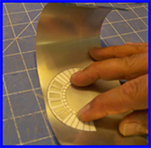
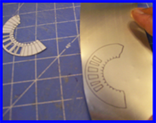
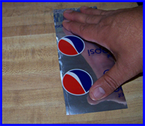
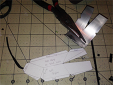
Place your cans with the print side down and place the first template onto the can. Hold it down as shown to the right and trace the part onto the can using a fine tipped marker or Sharpe. Remove the template piece to find the traced part ready to cut out from cans.
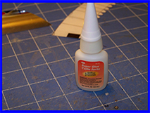
Again you will need to use a good Super Glue while making this model. I have used Loctite Gel, Testors Super Glue and even Super Jet and those brands all work sufficiently. Testors brand is pictured below:
What’s do you do if your can surface isn’t big enough for a certain part?
Well, to make it short and sweet, you create a panel of cans to accommodate a larger part. Here’s how I do it:
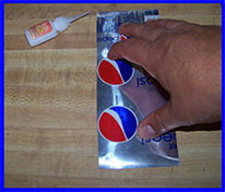
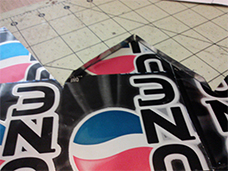
To glue a panel of cans, start by placing your first can on a flat surface with the print side up as shown in the picture. While you are holding it flat, take your super glue and make a line of beaded super glue from the top of your can to the bottom as shown.
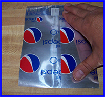
Finally, while you are still holding down the first can, take a second can and put it into position over top of the line of glue that you made on the first can. You will need to carefully run your fingers across this new seem starting from the bottom and working your way up being mindful not to get glued. The point of doing this is to smooth out any bulges so that you have a completely flat can surface to work with. Once your new can panel looks like the one pictured below, you must now weigh down your can panel until your super glue sets. The added weight will make your new panel stronger and easier to work with. I usually keep a stack of encyclopedias lying around and immediately place them over the newly created panel for at least 3-5 minutes until I am certain the glue has had adequate time to set. To make a larger panel, simply repeat this process by adding as many cans as you need until your can surface is long enough for the template parts in question.
What glue should one use for working with cans?
This question is one that soda can modelers will no doubt debate until the end of time. Some prefer Quick grip while others like high temperature hot glue. Personally, I prefer Super glue brands such as Loctite Gel, Super Jet and even Testors. I have found that the Super Glue gel works best for me and the one thing that you must take care is not using too much or else you will produce the tell-tale white residue from overuse. Everyone has their own preference so you will have to experiment to see what works best for you.
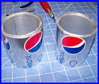
How do you prepare your cans to work with them?
The first thing that I normally do is pick out the cans that I am going to use, inspecting them for dents, dings or any blemishes that would take away from building a model. Once I have chosen my cans, I then wash them in the sink using dish soap and warm water. I let them sit on the counter for a few minutes with the opening facing down on some paper towels before I move onto the next step; shelling the cans.
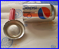
pair of scissors rather than attempting to cut them with a hand tool such a Dremel. As shown on the picture to the right, I lay the can on its side, poke the Hobby knife blade into the can and rotate it as I cut until the bottom comes off. I repeat this with the top of the can until only the middle part remains. I then make a vertical cut through the can on the seam of the can which is usually easy to find near the nutrition facts. The last step is to cut off the edge of the cans at the top and the bottom about 1/8th of an inch to remove the access material from cutting the top and bottom off. When completed, your cans should look like mine below. Notice that the edges are completely smooth and the frayed edge has been cut off on both ends:
Can you use chemicals to strip off the paint from the cans?
I have experimented with this briefly even though this takes away from the novelty of building with cans. But using certain chemicals, you can actually remove the painted surface. However, in my humble opinion it a messy and clumsy process that isn’t worth all the effort put into it. One, you remove any evidence of the fact that you are working with soda or beer cans and secondly, your surface will be that much harder to get the adhesives to work with. My advice is to avoid this step altogether and simply use hobby paint to spray over your cans if you are looking for a more realistic effect.
Building the model using a Fiddler’s Green Template (F-117 Nighthawk)
Tools You will need:
· Ruler or other straight edge
· Needle Nose pliers
· Ball Point Pen
· Fine Tipped Sharpe
· A sharp pair of scissors
· Hobby Knife
· Hobby Super Glue such as Loctite Gel, Testors Super Glue or Super Jet
· Something to round your can pieces. I use a golf putter or a wooden dowel.
Materials you will need:
· clean, undented soda or beer cans
· Clear Vinyl found in most fabric departments at Wal-Mart
· Aluminum Sheeting from the roofing section of your local hardware store. (I use the 10x10 roll made by Gibraltar Products)
Building the F-117 Nighthawk out of cans
Construction lower fuselage surface
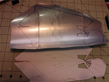
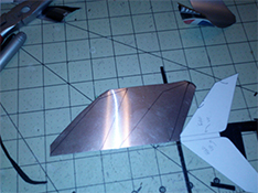
- Start by tracing the lower fuselage surface (cut off the fold over sections first) onto a set of can panels that you have previously created as shown in the FAQ section. One piece will serve as the top while the other will serve as the bottom piece. You will also need to trace a lower fuselage surface out of your aluminum sheeting material which will go inside of the two corresponding pieces traced onto the can material.
- Once you have traced out all three pieces, it is then time to begin the assembly by first test fitting the aluminum lower fuselage surface to one side of the can lower fuselage surface. Trim the aluminum sheeting to fit slightly inside of your can material and when happy with the fit, glue the aluminum sheeting to the can material.
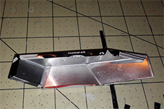
- Turn your lower fuselage surface over so that the side with the aluminum sheeting is facing up. Test fit your remaining lower fuselage surface over the top of the aluminum sheeting. Trim as needed and glue into position. Your completed assembly should look as shown in the picture below:

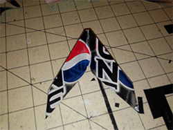
Construction of the upper fuselage section
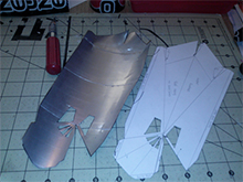
- Using the upper fuselage template, trace the upper fuselage piece onto your can panel created using the FAQ section. For the upper fuselage, you will need a panel of 5 cans.
- After tracing the piece onto your panels, cut out the piece carefully from your can panel and then using a sharp hobby knife, carefully cut out the cockpit windows so that the piece looks as shown below.
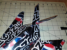
- Folding this fuselage piece is tricky and will require very precise and crisp folds to achieve the unique shape of the F-117. It will also require that some lines are cut to free up tabs especially at the rear of this piece. Review all lines marked score, fold under and cut and make certain to follow the directions precisely.
- Using a straight edge, make all required folds, scores and glue all tabs to achieve the proper fuselage shape. When completed, the upper fuselage should look as shown below:
- You will notice that the end of the lower fuselage surface has two tabs at the very rear tip. As shown in the top picture, you will need to cut these tabs off of the aluminum sheeting piece as well as the top can piece so that you can use a straight edge to bend the remaining two tabs upward.
- The next thing you will need to do, is to reinforce the inside of your upper fuselage piece once you have completed all of the folds, glued all of the tabs and placed your clear vinyl in the cockpit windows. Reinforcing the upper fuselage piece will give your model strength, but will also make your folds look sharper thus giving your model greater definition and appearance.
- Once you have completed these details it is now time to attach your upper fuselage piece to the lower fuselage surface.
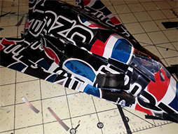
- The first step in mounting the upper fuselage piece to the lower fuselage surface is to line it up by aligning the nose of the upper fuselage so that each corner of the lower fuselage surface as shown in below. The rear of the upper fuselage piece will need to be lined up by aligning the center fold to the center point of the two tabs you folded upwards in the previous step.
- Test fit the two fuselage pieces together. Finally, bend in your mounting tabs until your upper fuselage sits straight and flush on your lower fuselage surface. When happy with the position and the fit, glue the upper fuselage piece into position. When completed, your model should look as shown in the bottom two pictures.
Adding the Nose piece
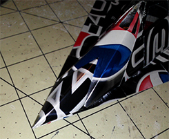
- To make the unique nose piece of this aircraft use the template provided to trace the piece onto your can material. To create the piece, first use a straight edge to fold the piece lengthwise, and then fold the four tabs inward until your nose piece looks as shown to the pictures below.
- Align and test fit your nose piece so that it sits flush on the lower fuselage surface, upper fuselage and is centered as well. The final position is indicated in the picture below. When you have the nose piece aligned properly, glue it into position as shown.
Adding the tail assembly
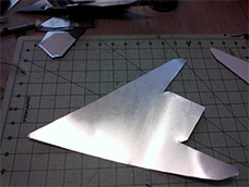
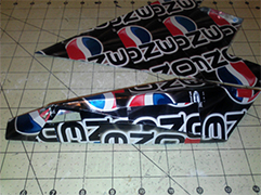
- To make the tail assembly, first use the template provided (cut off the fold over sections) to trace out a top and bottom piece out of can material and as shown in the picture below. Also trace out two corresponding pieces out of the aluminum sheeting material to reinforce your tail assembly as shown.
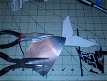
- Assemble the pieces by cutting all of them out and then gluing the aluminum sheeting pieces to the inside of one of your can tail pieces created with your template. Then take the remaining can piece and glue it over the top of your assembly thus sandwiching the aluminum sheeting between the cans.
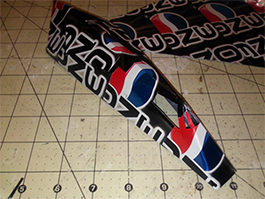
- Once the assembly is dry, you will need to take a straight edge and carefully bend the assembly as shown in the picture below since the F-117 has a unique twin tail that angles upward slightly. Once this step is completed it is now ready to be mounted to the top of your upper fuselage piece
- To add the tail assembly to the rear of the upper fuselage, center it on the farthest rear point of the upper fuselage directly on the center crease that you made when in the previous steps. The tail assembly should be glued flush against the downward slope of the center fold line. Test fit and glue into position when satisfied with the fit. Your tail should now look as shown in the picture below.
The engine intake assemblies
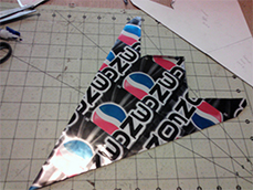
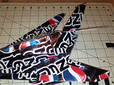
- To begin the final step of the engine assembly, use the templates provided to trace and cut out a left and right engine piece.
- Once you have carefully cut out the two engine pieces, cut along the line at the front of the intake as this will allow you to make all of the critical folds that are required to give these engine pieces their unique shape.
- Once you have completed the folds, scores and glued all tabs, your engine intake should have the unique shape as shown in the pictures below. The tabs should be folded in so that your engines can mount flush against the side of the upper fuselage piece and also to the lower fuselage surface.
- As shown in the next picture, reinforce the inside of the engine intake pieces to give them shape and definition. You can use either aluminum sheeting or can material, but doing this will give your model volume and depth.
- Test fit the engine intake as shown in the bottom picture. The engine should mount flush against both the upper fuselage and the lower fuselage surface piece as well. Adjust your folds and tabs until the engine sits flush to both surfaces. When you are satisfied with the placement, glue into position and repeat these steps for the engine intake assembly on the opposite side.
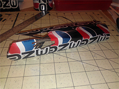
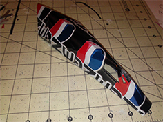
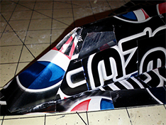
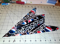
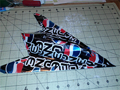
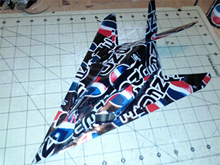
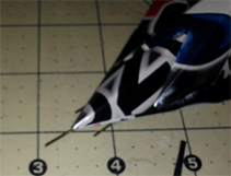
- When you have both engines glued into position, your model should look as shown in the pictures below. At this point your model is just about completed. All that is left to do is remove any glue residue with nail polish remover and if you like, you can create the pitot tubes at the front of the aircraft by cutting some strips of thin metal wire and gluing them to the underside of the forward fuselage.
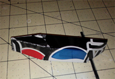
The Pitot tube configuration is shown in the picture below:
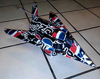
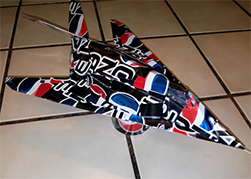
The completed Fiddler’s Green F-117 Nighthawk built out of Coke Zero cans